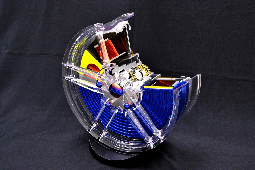
LIGHT CUT MODEL STYLE 17 INCH WHEEL MOTOR Mechanism design
CROSS-SECTIONAL MODELS
We offer extremely lightweight cross-sectional models.
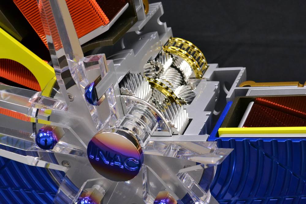
Cross sectional “cut models” are made of ferrous and non-ferrous metals. Achieved with expert craftsmanship using resin and decorative processing.
Advantages:
Compared with ferrous or non-ferrous metal, it can be significantly reduced in weight. ・ Approximately 1/7 of iron ・ About 1/2 made of aluminum Benefits of weight reduction ・ Improved flexibility in exhibition methods ・ Reduction of transportation cost ・ Reduction of handling risk Further weight reduction -It is possible to further reduce the weight by hollowing out the part that cannot be seen in the structure. Design ・ Expose the mechanism by designing which parts are transparent and partially transparent. -Incorporate LED lighting inside the parts to make them stand out. ・ Half evaporation plating and internal lighting are combined to show the surface design and internal structure at the same time by turning the lighting on and off. Maintenance Free ・ Because no iron or non-metal is used, no rust is generated and the appearance can be maintained.
Material used Polycarbonate (transparent, black) Transparent Stereolithography Material (TSR-829)
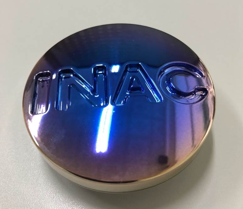
Use method Cutting (3 axis, 5 axis processing) 3D printer (transparent stereolithography) Polycarbonate transparent treatment Aluminum vapor deposition plating, painting (solid, color clear, gradation, etc.) Titanium heat gradation decoration
Please feel free to contact us. Adequate support will be provided by our experienced designers until prototype completion.
A quality inspection is performed. At INAC, where quality comes first, we use CMMs, gauges, and other equipment for precision checks.
STEP4: Post-Processing and Finishing
Finishing is done by removing the supports, polishing, and applying transparency treatment. It is also possible to paint and apply plating to the formed product.
STEP3: UV-Laser Print Formation (SLA Process)
Output: The product is formed by irradiating the liquid with a laser beam of UV light and laminating it. The conditions of the external environment, such as room temperature and humidity, must be maintained.
STEP2: Model Program Generation and Support Adjustment
A program for model formation is created. Depending on the shape, it may be necessary to adjust the degree of tilt and the position of the supports.
STEP1: CAD File Submission
Upload your CAD to our online quoting platform.
STEP 3: Rendering and Scene Integration
We can also handle exterior modeling and interior structure design based on illustrations.
After creating the 3D models, we can create a rendering to fit a scene. We can deliver images even if we do not proceed with production.
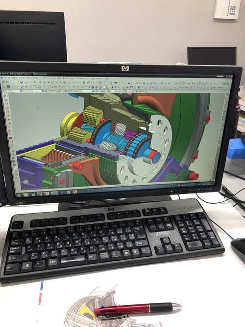
STEP 2: Detailed Design and 3D Modeling
Once the design is determined, drawings and 3D models will be created.
The structure will be examined, taking into consideration not only the external design but also functionalities such as mating and sliding.
STEP 1: Initial Design Consultation
The first step is a meeting to discuss the project. Drawings are not required for this meeting. We will create a design from a sketch based on the overall image and concept that you have in mind.
STEP5: Quality Assurance and Inspection
We perform quality inspections. At INAC, where quality comes first, we use CMMs, gauges, and other equipment for precision checks.
STEP4: Post-Casting Finishing
Vacuum casting materials are cured and then taken out of the silicone rubber mold. Then we perform finishing such as deburring and gating, and they are made into finish products.
STEP3:Material Injuction
Liquid casting material is injected into the silicone rubber mold in a vacuum environment.
STEP2: Mold Preparation
The silicone mold is cut open into a male and female mold, and the master model is removed.
STEP1: Mold Creation
The master model is fixed to a wooden frame and silicone is poured to create a mold.